The next step in the flight controller project is to program the ATmega4809 for 4-channel servo control. I could have used a PWM control IC like the PCA9685 in this module, but to keep the hardware design simpler I am driving the servos directly from the ATmega4809.
This post is a follow-on to the Simple Multi-Channel Pulse Width Capture with ATmega4809 post to make a passthrough controller.
Code: https://github.com/benjohnemmett/Wingman/releases/tag/pwm_pass_through
Design
The servo motor control pins need to send 5 volt pulses at 50Hz with a pulse width between 1ms and 2ms. The 50 Hz rate means that there is a period of 20ms between the start of each pulse in a given channel.
The ATmega4809 doesn’t provide enough timers to dedicate one for each PWM channel. So my plan is to use one timer for all four servo control channels by driving the pulses sequentially.
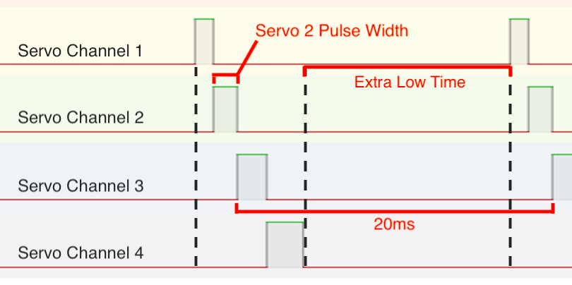
The basic idea is to use the interrupt service routine (ISR) for Timer/Counter A (TCA) that is triggered when TCA reaches a certain value called TOP. The program is initialized by resetting TCA, setting the TOP value to the desired width of the first pulse, and (of course) enabling interrupts.
When the interrupt is triggered, the current servo channel will be dropped to logic LOW and the next servo channel will be set to logic HIGH. TCA will be reset and TOP will be set for the desired pulse width of the next channel. This continues for all four channels. Then the rest of the 20ms needs to complete with all four channels LOW. So following similar logic as before, all four channels are set LOW, TCA is reset, and TOP is set to the desired extra LOW time needed. The next time the interrupt is triggered, the process starts over again with serovo channel 1.
Timer Resolution
To use TCA for servo control there needs to be enough time range to cover the largest possible span of the extra LOW time. This would occur when all four channels have a minimum pulse width.
Max(Pulse_{extra}) = Pulse_{total} - N * Min(Pulse_{channel}) = (20 - 4*1) ms = 16ms = 16000usSo the max time range of TCA must be greater than 16000us. I’d also like time resolution to be no greater than 1us. Resolution and range can be calculated like so:
Resolution_{TCA} = \frac{ClockDiv_{TCA}}{F_{CPU}}Range_{TCA} = Resolution_{TCA} * 2^{BitWidth_{TCA}}Using those equations, I made a table of clock divider options for F_CPU = 20MHz and TCA BitWidth = 16:
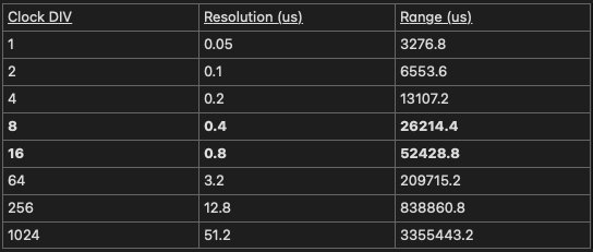
The two clock divider options that meet both constraints are 8, or 16. I initially used 8 for higher resolution, then while debugging I switched to 16 for some reason. Either option appears to be working fine so I’m sticking with 16 for now.
Hardcoded PWM Out Test
I ran a very basic test which was to output a unique fixed pulse width on each channel. I set them to 1.0ms, 1.3ms, 1.6ms, 2.0ms.
The logic analyzer shows good results. They are generally close to the width that I hardcoded them to be. There was initially a consistent bias of about 10us which I attribute to the extra time spent in the interrupt service routine to switch pin values and update state. This bias was removed by adding an extra term, called INT_TRANSITION_CYCLES.
uint16_t out_1 = (uint16_t)((float)in_1 * MICROS_TO_TCA_TICKS) - INT_TRANSITION_CYCLES;PWM Passthrough Test
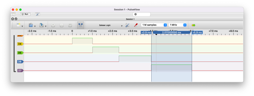
The next step is to combine the PWM capture logic with the PWM out logic to make a passthrough program. I hooked up my RC receiver to the input pins on the ATmega4809 and modified the code to output the same value that was read in. I inspected the results with the logic analyzer.
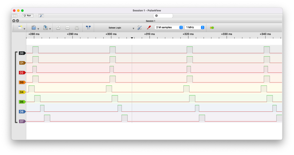
I spot checked the input and output capture and found promising results. The top four channels are the signal from the RC receiver going into the ATmega4809, the bottom four channels are the ATmega4809 output. The output is generated at near 50Hz and appears to follow in the input signal pulse widths which changed as I moved the RC transmitter control sticks around.
It is difficult to fully check the logic analyzer capture since there is so much data and it is difficult to see small errors in pulse width on the visual plot. I would like to find a way to parse the captured logic analyzer data in a more general purpose scripting language (Python or Matlab) and do more thorough data analysis at some point. For now, I’m satisfied enough to move forward.
RC Plane Control Passthrough Test
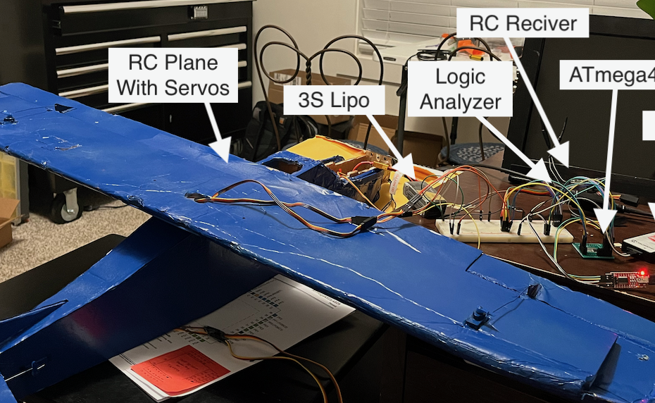
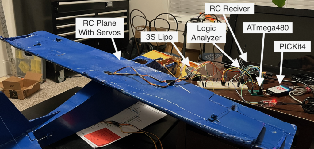
The final test is to know if this PWM out can control an RC plane servos and ESC. This test setup quickly got messy as the picture below shows.
Here is the diagram of the test layout (Logic analyzer & PICKit 4 not included for simplicity)
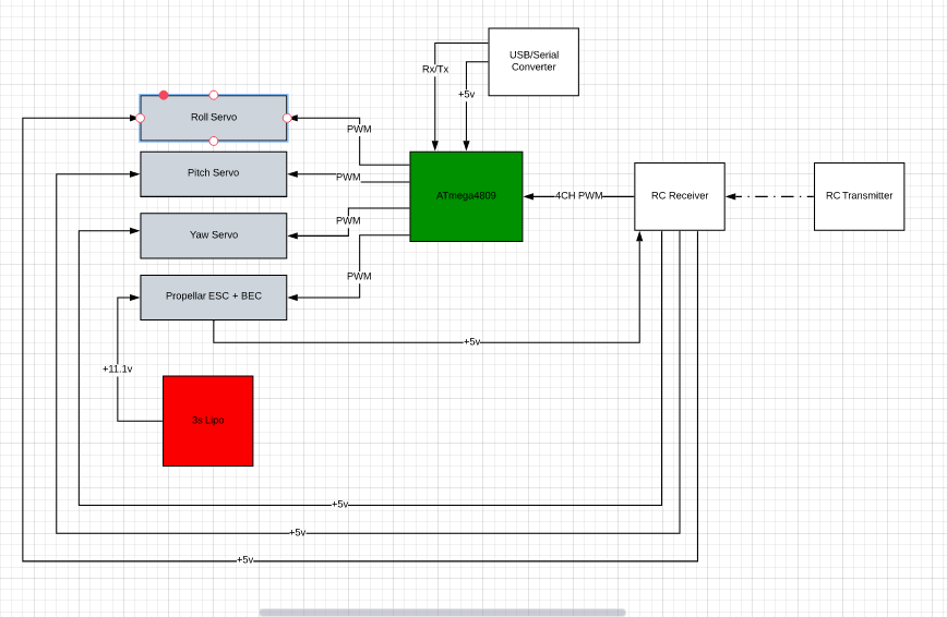
The servos are powered from the Battery Elimination Circuit (BEC) that is integrated with the Electronic Speed Controller (ESC) for the propeller motor. This is a typical power setup for an RC plane. However, to keep the power to the ATmega4809 clean, it has a separate power supply from my FTDI USB to Serial converter.
The PWM passthrough test with all three servo motors running at the same time was successful. The servo motors responded to the transmitter commands just as if the receiver was directly connected to the motors, only a bit more jittery. The one hang up on testing came when trying to test the ESC control. Since the power for all motors is supplied by the ESC through the receiver, I had to disconnect the ESC jumper from the receiver and run power through jumper wires. Apparently the jumper wires are not able to keep up with power demands because with this setup things stopped working well. The low power alarm on the transmitter sounded and all the motors moved sporadically. I verified that even in a normal configuration with the motors directly connected to the receiver, running power from the ESC through a set of jumper wires caused low power issues.
Overall, the test was a success. I plan to make custom jumper wires soon so that I can improve the test setup and run with all four PWM channels in passthrough mode.
Servo Motor Power Budget
In the final design I plan to have a separate power rail for the servos which is supplied by the ESC. To do that I need to know how much current the rail needs to carry. At this point, all I know is that I need more power than my cheap jumper wires can supply. To get a better estimate, I measure the current draw of each servo motor both while idling and moving.
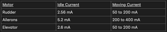
From this I estimate that the power rail needs to supply at least 800 mA of current. I will add margin design for at least 1A of current. I may also add an optional jumper to use the ESC power supply rail for the flight controller components in which case I would need to account for that power draw as well.